
Root Cause Analysis of Combined Impeller Looseness and Unbalance in an AHU Blower
A Metro Station Air Handling Unit (AHU) Blower Field Investigation
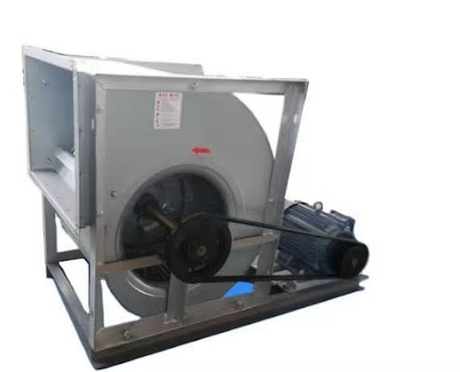
Belt-driven, simply supported AHU blower with induction motor drive
March 27, 2026 | Abu Dhabi, U.A.E.
N. Sasi Vardhan Reddy
Assistant Manager, Condition Monitoring Services
assetconditionmonitoring.com | powered by Technomax Middle East Engg. LLC
Abu Dhabi, UAE
Executive Summary
This case study documents the diagnosis and resolution of elevated vibration on a belt-driven, simply supported Air Handling Unit (AHU) blower operating at 713 rpm and driven by a 1465 rpm induction motor. The issue surfaced after a January 2025 startup that followed sandblasting/re-coating of the fan impeller and replacement of the fan bearings.
Initial vibration readings at the blower drive-end (DE) bearing reached 10.1 mm/s RMS (horizontal) and 10.3 mm/s RMS (vertical), dominated by a 1X synchronous peak consistent with rotor unbalance. A field balancing correction reduced the 1X amplitude but produced an abnormal noise from the impeller, prompting a shutdown and inspection that revealed all impeller cone bolts were loose.
After the cone bolts were re-tightened and the impeller re-balanced (65 g added at 0° on the fan non-drive-end (NDE) side), the fan DE 1X amplitude fell from 9.2 mm/s to 1.2 mm/s and the fan NDE 1X amplitude fell from 5.4 mm/s to 1.9 mm/s. A residual sub-synchronous peak at 8.5 Hz was subsequently traced, via bump testing, to a structural natural frequency of the flexible motor base rather than a rotor fault, and was confirmed to fall within acceptable vibration limits for the mounting type.
The root cause was an incompletely torqued impeller mounting during reassembly after maintenance, which produced a compound fault of mechanical looseness superimposed on unbalance. The case reinforces the importance of bolt-torque verification as a mandatory step after any impeller disassembly.
1. Background & Equipment Description
An AHU blower in a metro station uses a centrifugal fan to draw in fresh and return air, filter and condition it through cooling coils, and supply the conditioned air under pressure through ductwork to maintain ventilation, temperature, and air quality for passenger comfort.
The unit under investigation is a simply supported, belt-driven blower fitted with a damper system beneath the machine frame and driven by an induction motor. Key operating parameters are summarized below.
Parameter
Value
Blower running speed
713 rpm
Motor running speed
1465 rpm
Drive type
Belt drive (induction motor)
Support type
Simply supported, flexible base
Application
Metro station ventilation / temperature control
2. Problem Statement
Following the January 2025 startup — after sandblasting/re-coating of the fan impeller and replacement of the fan bearings — elevated vibration levels were observed at the blower drive-end (DE) bearing:
Horizontal: 10.1 mm/s RMS
Vertical: 10.3 mm/s RMS
The vibration spectrum showed a dominant 1X (running-speed synchronous) peak at the DE bearing. Vibration data could not initially be collected from the non-drive-end (NDE) bearing due to physical inaccessibility, and no abnormal sound was reported at that stage. Absolute phase analysis pointed toward rotor unbalance as the probable cause.
3. Investigation & Data Review
3.1 Initial Diagnosis — Unbalance
Based on the dominant 1X spectral peak and the absolute phase relationship between horizontal and vertical measurement planes, the diagnosis pointed to rotor unbalance. A trial balancing correction was applied to the fan impeller to offset the unbalanced force.
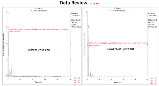
Route spectra recorded before cone-bolt tightening and balancing — Blower drive end (left, 9.2 mm/s RMS at 1X) and non-drive end (right, 5.9 mm/s RMS at 1X)
The balancing correction reduced the fan's 1X order amplitude, but an abnormal sound then began emanating from the fan impeller. As a precaution, the machine was stopped for a physical inspection of the impeller assembly.
3.2 Physical Inspection — Mechanical Looseness Confirmed
On inspection, the impeller cone bolts were found loose — all of the blower's mounting bolts had not been fully torqued, most likely during the impeller re-mounting carried out as part of the January 2025 maintenance.

Field inspection confirming looseness at the impeller cone bolt joint
This finding indicated a compound fault: mechanical looseness at the impeller-to-shaft interface superimposed on residual rotor unbalance — a combination that can mask or distort classic unbalance symptoms and mislead a diagnosis based on spectral data alone.
4. Corrective Actions Taken
All impeller cone bolts were re-tightened to the correct torque on site, and the earlier trial balance weight was removed.
Vibration data were re-collected after bolt tightening; with the NDE bearing now accessible, maximum casing vibration reached 7.7 mm/s (horizontal) at the DE bearing and 11.7 mm/s (horizontal) at the NDE bearing.
A fresh balancing correction of 65 grams was added to the fan impeller (NDE side) at 0° from the reference point to compensate for the residual unbalance force.
5. Verification & Final Results
Following cone-bolt tightening and the revised balancing correction, the 1X synchronous amplitude dropped sharply at both blower bearings:
Fan DE bearing: 9.2 mm/s → 1.2 mm/s (1X amplitude)
Fan NDE bearing: 5.4 mm/s → 1.9 mm/s (1X amplitude)
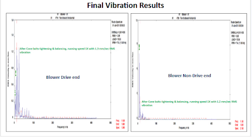
Final route spectra after cone-bolt tightening and balancing — Blower drive end (left, 1.3 mm/s RMS overall) and non-drive end (right, 1.2 mm/s RMS overall)
5.1 Overall vs. 1X Amplitude Comparison
Bearing Location (mm/sec RMS)
Before tightening impeller cone bolts
Before tightening cone bolts & before balancing
After Balancing
Overall | Fan 1X
Overall | Fan 1X
Overall | Fan 1X
At Motor NDE
H
2.4 | 1.0
2.9 | 1.6
3.6 | 0.6
V
5.5 | 2.5
5.4 | 0.8
4.3 | 0.5
A
6.4 | 3.4
6.2 | 0.5
6.6 | 0.4
At Motor DE
H
4.1 | 2.0
2.9 | 0.5
3.0 | 0.4
V
4.5 | 2.2
2.7 | 0.7
2.2 | 0.3
A
5.4 | 2.2
6.2 | 0.5
5.5 | 0.2
At Fan DE
H
10.1 | 9.2
3.7 | 1.7
2.6 | 1.2
V
10.3 | 8.9
7.7 | 1.6
6.8 | 1.1
At Fan NDE
H
N/A
11.7 | 5.4
8.5 | 1.9
V
N/A
5.4 | 4.4
3.0 | 1.4
A
N/A
6.5 | 1.2
5.4 | 0.6
Values in red mark the pre-repair fault condition; values in green mark the post-repair result after cone-bolt tightening and balancing.
6. Residual Vibration & Structural Resonance Check
Even after cone-bolt tightening and balancing, moderate vibration levels persisted at both blower bearings, with spectra from the motor and fan bearings showing a dominant sub-synchronous peak at 8.5 Hz — suspected to be a structural natural frequency excited by a flexible base.
A bump test was carried out on the machine structure to confirm this. Testing on the motor base frame, motor, and fan casing identified natural frequencies of 4.3 Hz, 6.16 Hz, and 8.22 Hz on the motor base frame and motor. During normal operation, the 8.22 Hz resonance is excited by the flexibility of the base frame.
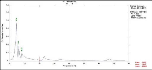
Bump test response on the motor base frame, showing natural frequencies at 4.34 Hz, 6.16 Hz, and 8.22 Hz
Although the machine experiences resonance during operation, the observed vibration levels remain within acceptable limits for this type of mounting, and no further structural intervention was required.
7. Conclusions
During January 2025 major maintenance, the impeller was removed from the shaft for sandblasting/coating and the blower bearings were replaced.
During subsequent blower re-assembly, the maintenance team was unable to fully tighten the impeller mounting; all blower cone bolts were later found loose during inspection, contributing to both unbalance and elevated vibration.
The fault presented initially as classic unbalance (dominant 1X peak), but a first balancing attempt uncovered an underlying mechanical looseness condition once abnormal noise appeared — underscoring the value of combining vibration diagnostics with physical inspection when a correction does not fully resolve symptoms.
Root cause: incompletely torqued impeller cone bolts following post-maintenance re-assembly.
8. Lessons Learned & Recommendations
Always ensure all impeller cone bolts are properly and fully tightened during assembly after maintenance.
Verify bolt torque after any disassembly activity, such as impeller removal for cleaning, coating, or bearing replacement.
Improperly tightened bolts can independently produce unbalance, abnormal noise, and elevated vibration — treat unresolved or evolving symptoms after a corrective action as a trigger for physical inspection.
Include bolt-torque checks as a mandatory item on the pre-startup maintenance checklist.
Where a machine sits on a flexible base, consider a bump test as part of commissioning to identify natural frequencies that may coincide with operating speed or its harmonics.