
What Is Impeller Dynamic Balancing?

How Modal Analysis in Condition Monitoring Detect Structural Problems

How partial discharge affects Insulation performance
What Types of Motor Faults Can MCSA Detect?
Gearbox Vibration Analysis: How To Find Gear Faults Through Vibration Signals

Construction Vibration And Noise Monitoring UAE
What Is Pump Cavitation and How to Avoid It
Why Pump Alignment Is Critical for Reliable Industrial Operations ?
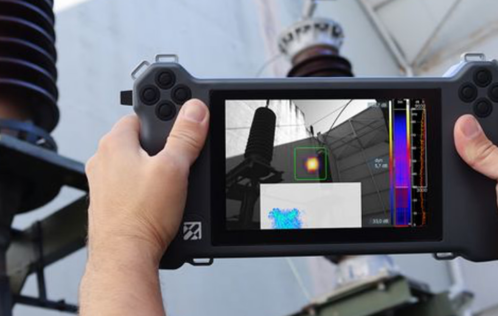
How Does an Acoustic Camera Work?

What is Infrared Thermography for Electrical Inspection?

What is Partial Discharge Testing?
Impeller dynamic balancing is the process of identifying and correcting uneven mass distribution in an impeller while it rotates. It helps reduce vibration, minimise stress on bearings and shafts, and ensure smooth, stable, and reliable equipment operation.
Impeller dynamic balancing is important for the performance, stability, and reliability of rotating equipment. An impeller must have its mass distributed evenly around its axis of rotation to minimise imbalance during operation.
When the mass is unevenly distributed, rotation generates centrifugal forces that cause excessive vibration and place additional loads on bearings, shafts, and other connected components.
If imbalance is not found or corrected during maintenance or repair, it can be a likely source of future mechanical problems like premature component wear, reduced operating efficiency, and increased maintenance requirements. Since impeller design, size, and operating conditions are different, the best balancing method must be chosen to achieve stable rotation and reliable equipment performance.
Dynamic balancing is commonly performed on impellers used in centrifugal pumps, compressors, fans, blowers, and other rotating machinery. These are equipment operating at high speeds or under demanding industrial conditions, where even a small mass imbalance can increase bearing loads, cause component wear, and affect overall equipment reliability.
Identifying/correcting mass imbalance reduces unwanted vibration, protects critical components, and supports smooth equipment operation. Proper impeller balancing improves mechanical reliability, extends component service life, and supports more consistent operating performance.
What Is Impeller Imbalance?
Impeller imbalance is a condition where the mass of an impeller is not evenly distributed around its axis of rotation. As the impeller spins, this uneven distribution creates centrifugal forces that can cause excessive vibration, increase loads on bearings and shafts, and affect the overall performance of the equipment.
Imbalance can develop for many reasons, for instance, uneven material distribution, deposits on the blades, corrosion, erosion, or damage during operation, among others.
These imbalance issues must be inspected and addressed properly. If left uncorrected, it can accelerate component wear, reduce operating efficiency, and increase the risk of unexpected equipment failure. Dynamic balancing is a way to correct this imbalance, letting the impeller rotate more smoothly and reliably.
Impeller balancing can be of two types: static and dynamic imbalance. Static imbalance occurs when the centre of mass is offset from the rotational axis, causing the impeller to have a heavier side. Dynamic imbalance develops when the mass distribution creates an unbalanced force and couple during rotation, often requiring correction in two or more planes.
These conditions can arise during manufacturing due to material inconsistencies, dimensional variations, or machining errors. During operation, corrosion, erosion, blade damage, and the accumulation of dirt or deposits can further disturb the impeller's mass distribution. The following are the common causes that may lead to impeller imbalance:
Manufacturing tolerances
Uneven material removal
Corrosion and erosion
Cavitation damage
Deposits and fouling
Repairs or welding
Wear during operation
Improper machining
Static vs. Dynamic Impeller Balancing
Static balancing is usually suitable for simpler, single-plane imbalance, and dynamic balancing is preferred when an impeller requires correction in two or more planes. The appropriate method depends on the impeller's geometry, operating speed, and applicable balancing requirements.
Comparison
Static Impeller Balancing
Dynamic Impeller Balancing
Definition
Corrects an imbalance when the impeller's centre of mass does not align with its axis of rotation, causing a heavy spot.
Corrects imbalance caused by uneven mass distribution along the impeller's rotating axis, which can produce unbalanced forces and couples.
Type of imbalance detected
Static imbalance, where the impeller tends to rotate until its heavy spot moves to the bottom.
Couple imbalance and dynamic imbalance, including combined static and couple imbalance.
Suitable applications
Narrow impellers, thin discs, and other rotating components where a single-plane correction can properly correct imbalance.
Wider impellers, high-speed rotating components, and applications where imbalance in multiple planes must be corrected.
Measurement method
The impeller is placed on a level, low-friction surface or balancing stand to identify its heavy spot.
The impeller is rotated on a balancing machine that measures vibration or centrifugal force to check the magnitude and location of imbalance.
Correction method
Material is removed from the heavy area or added to the ideal location to achieve balance.
Material is removed or added in one or more correction planes to reduce both force and couple imbalance.
Limitations
Cannot reliably identify or correct couple imbalance, which makes it unsuitable for many wider or high-speed impellers.
Requires specialised equipment and setup, and might take more time and cost than static balancing.
From the above table, it is quite clear that for high-speed or wider impellers, dynamic balancing is particularly suitable because uneven mass distribution can create unbalanced forces in multiple planes along the rotating axis. At high speeds, these forces increase and can cause excessive vibration, bearing wear, shaft stress, and premature equipment failure. This means Dynamic balancing services can identify the magnitude and location of the imbalance in each correction plane, allowing the necessary adjustments to reduce vibration and improve the reliability, stability, and service life of the rotating equipment.
Why Is Dynamic Balancing Important for Impellers?
Dynamic balancing is essential for impellers because it corrects uneven mass distribution, reduces vibration, and ensures smooth, reliable equipment operation, maintaining mechanical stability, minimising component stress, and improving rotating equipment reliability. Let us take a closer look at some of the core benefits of dynamic balancing for impellers:
Reduces vibration: Dynamic balancing minimises vibration caused by rotational imbalance.
Protects bearings and seals: Reduces vibration-induced wear on bearings and seals.
Reduces shaft loading: Minimises dynamic forces acting on shafts.
Prevents premature component failure: Reduces mechanical stress and fatigue-related damage.
Improves equipment reliability: Promotes stable and reliable rotating equipment operation.
Reduces noise: Minimises noise generated by mechanical vibration.
Improves operating efficiency: Reduces energy losses associated with excessive vibration.
Extends equipment service life: Limits wear and prolongs component service life.
Supports predictive maintenance: Enables more reliable vibration-based condition assessments.
Read Our Case Study On Impeller Dynamic Balancing
What Happens When an Impeller Is Out of Balance?
When an impeller is out of balance or has uneven mass distribution, its rotation generates unbalanced centrifugal forces that increase with operating speed. Meaning these forces cause intense vibration which is undesirable for machine parts, especially placing additional loads on the shaft, bearings, seals, and coupling. As the issue persists, the component wears, mechanical connections loosen, and critical parts get damaged, leading to unexpected equipment failure and costly downtime.These are the common symptoms of an unbalanced impeller to look for:
Excessive radial vibration: Unbalanced forces causing increased vibration perpendicular to the shaft axis.
Increased bearing temperature: Additional dynamic loads increasing friction and bearing stress.
Seal leakage: Shaft vibration disrupting seal contact and sealing performance.
Abnormal noise: Mechanical vibration generating unusual humming, rattling, or noise.
Shaft movement: Unbalanced forces causing excessive shaft deflection and movement.
Coupling problems: Vibration accelerating coupling wear and loosening connections.
Premature bearing failure: Continuous dynamic loading shortening bearing service life.
Impeller Dynamic Balancing Process: Step-by-Step
Dynamic balancing is a meticulous process that needs accurate measurements, careful preparation, and precise correction of mass distribution. It plays a vital role in maintaining the mechanical health of critical rotating equipment, where even a small imbalance can induce significant forces at high operating speeds. Which is why following a systematic procedure is essential to reduce vibration, protect sensitive components, and ensure reliable equipment performance.
The actual process begins with a thorough visual examination of the impeller to check for cracks, corrosion, erosion, material deposits, and rule out any other signs of physical damage. These defects can affect mass distribution and might mean underlying structural problems. Any significant damage is to be assessed before proceeding with balancing.
Step 2: Cleaning and Preparation
The impeller is to be cleaned and conditioned to remove accumulated dirt, scale, oil, and other deposits that could also affect its mass distribution. This is an important step because the balancing measurements will only reflect the impeller rather than unwanted material attached to its surfaces. Proper preparation also avoids any measurement inconsistencies during the balancing process.
Step 3: Dimensional Inspection
Critical dimensions, including impeller diameter, width, bore size, and mounting features, are checked against the relevant specifications. These measurements confirm the impeller is suitable for mounting and that its layout or geometry has not been changed by wear or damage. Dimensional accuracy is a decisive element essential for reliable balancing results.
Step 4: Mounting on the Balancing Machine
Then the impeller is securely mounted on a suitable dynamic balancing machine using the correct fixtures and mounting arrangement. Accurate positioning is important to minimise errors caused by eccentric mounting, runout, or improper alignment with the rotational axis. Incorrect mounting can distort the readings and lead to unnecessary or ineffective corrections.
Step 5: Initial Spin Test
The mounted impeller is rotated at the balancing machine's specified test speed to measure its initial imbalance. Sensors detect the resulting vibration or force, establishing the extent of the imbalance and its distribution across the correction planes. These readings act as the baseline for determining the required adjustments.
Step 6: Identify the Imbalance
The balancing system checks the magnitude and angular position of the imbalance using the measured signals. For two-plane balancing, it also identifies the correction required in each plane to address both force and couple imbalance. This information guides the technician in selecting the appropriate correction locations and amounts.
Step 7: Correct the Imbalance
Corrections are made based on the balancing machine's results and the impeller's design needs. Depending on the material and construction, this might involve controlled material removal through drilling, milling, or grinding, or adding balancing weights where allowed. Each adjustment is to be carefully calculated to avoid excessive material removal or introducing a new imbalance.
Step 8: Verification Run
After the corrections are completed, the impeller is rotated again to measure remaining imbalance. The results are compared against the specified acceptance levels to confirm that the required balance quality has been achieved. If the residual imbalance exceeds the permitted tolerance, further adjustments and verification runs would be necessary.
Step 9: Balancing Report
A balancing report documents the results and provides a record of the work performed. It typically includes the initial imbalance, corrections made, residual imbalance, balancing speed, correction planes, and applicable acceptance criteria. This documentation supports quality control, traceability, and future maintenance assessments.
How Is Impeller Imbalance Measured?
Impeller imbalance is measured using a dynamic balancing machine or vibration analysis equipment that checks the rotor's response during rotation. Checking Vibration amplitude, phase angle, and unbalance amount determines the severity and location of the imbalance and gives the corrections required. But issues like mechanical looseness (for instance, at the impeller-to-shaft interface) can distort vibration readings, making it important to inspect mounting conditions and verify minute details, rather than relying on spectral data alone.
Key Parameters Used to Measure Impeller Imbalance
Vibration amplitude: Indicates the magnitude of vibration produced during rotation. Higher amplitudes can indicate major imbalance, although looseness and other mechanical faults can produce similar symptoms.
Phase angle: Identifies the angular position of the vibration relative to a reference point on the rotating shaft. Particularly useful to locate the heavy spot and determine where balancing corrections should be applied.
Unbalance amount: Represents the product of the unbalanced mass and its distance from the rotational axis. It is commonly expressed in units such as g·mm or g·cm and determines the required correction.
Correction radius: Refers to the distance from the rotational axis at which balancing material will be added or removed. The selected radius determines how much mass must be adjusted to correct the measured imbalance.
Correction plane: Identifies the axial location where the balancing adjustment is made. Single-plane correction may be sufficient for narrow rotors, but wider impellers would be needed for two-plane balancing to address both force and couple imbalance.
Residual unbalance: Refers to the imbalance remaining after the correction process. It is checked against the applicable balance quality requirements to confirm whether the impeller meets the specified acceptance criteria.